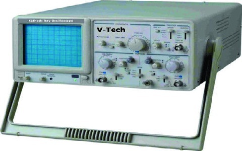
CRO Stands for Cathode Ray Oscilloscope
When it comes to electronic test instruments, the world of signals and voltages has found a reliable observer in the form of a Cathode Ray Oscilloscope, commonly known as a CRO. As you explore the intricate workings of this device, the cathode ray tube, vertical and horizontal deflection systems, and signal input connections come into view like pieces of a technological puzzle waiting to be solved. But what makes the CRO truly stand out is not just its components; it’s the way it unravels the mysteries of fluctuating signals in a dynamic display that keeps you captivated, eager to understand its full potential.
Origins of CRO Technology
- The origins of CRO technology date back to the late 19th century when scientists began experimenting with cathode ray tubes. These early explorations laid the foundation for the evolutionary advancements that would lead to the development of the modern Cathode Ray Oscilloscope (CRO). By the mid-20th century, CRO technology had made significant strides, allowing for more precise measurements and analysis in various fields.
- The practical applications of CRO technology are vast and essential in today’s technological landscape. From electronics to medicine, CROs play a crucial role in analyzing and visualizing electrical signals. Engineers use CROs to troubleshoot circuits, measure signal voltages, and observe waveforms. In the medical field, CROs are used in electrocardiography (ECG) to monitor heart activity accurately.
- The continuous evolution of CRO technology has made it an indispensable tool for professionals across diverse industries. Its ability to provide real-time visual representation of electrical signals has revolutionized the way data is analyzed and interpreted.
CRO Stands for Cathode Ray Oscilloscope
Functionality of a CRO
- Building upon the foundational origins of CRO technology in the late 19th century, the functionality of a CRO lies in its ability to visually display electrical signals in real-time for precise analysis and measurement. CRO applications span across various fields such as engineering, physics, medicine, and telecommunications. In troubleshooting electronic circuits, CROs are invaluable tools for identifying signal distortions, voltage fluctuations, and waveform abnormalities.
- The CRO display, consisting of a cathode ray tube, provides a visual representation of the input signal allowing for detailed waveform analysis. Calibration of a CRO ensures accurate measurements by adjusting the vertical and horizontal deflection to represent voltage and time correctly. Understanding the calibration process is crucial for obtaining reliable data from the CRO.
Components of a CRO Diagram
- Exploring a CRO diagram reveals its intricate components that play crucial roles in signal visualization and measurement accuracy. Two essential components depicted in a CRO diagram are voltage measurements and display options. Voltage measurements refer to the capability of the CRO to accurately measure voltages across the horizontal and vertical axes, allowing for precise analysis of electrical signals. The voltage measurements are typically displayed on the screen, aiding in waveform analysis and signal characterization.
- On the other hand, display options encompass the various settings and controls available on the CRO for customizing how the signals are visualized. These options include adjusting the timebase to control the horizontal sweep speed, altering the vertical sensitivity to scale the voltage measurements, and choosing different trigger modes to stabilize the waveform display. By manipulating these display options, users can optimize the visualization of signals on the CRO screen to extract detailed information for analysis and troubleshooting purposes.
Importance of Vertical Deflection System
- Within a cathode ray oscilloscope (CRO), the vertical deflection system plays a critical role in accurately displaying voltage variations over time. The vertical sensitivity of the CRO determines how much vertical deflection occurs for a given input voltage. This sensitivity can be adjusted to ensure that the voltage signal is displayed clearly and accurately on the screen. The deflection coils in the vertical deflection system are responsible for moving the electron beam vertically on the cathode ray tube, allowing for the visualization of the voltage signal. Proper calibration of these coils is essential for precise measurements and reliable display of waveforms.
- The vertical deflection system also contributes to the overall display resolution of the CRO. By controlling the vertical positioning of the electron beam with precision, it enables the user to observe small changes in voltage over time. This level of detail is crucial in various applications, such as analyzing electronic circuits, signal processing, and waveform characterization. Therefore, understanding and utilizing the vertical deflection system effectively is fundamental for accurate voltage measurements and waveform analysis on a CRO.
Signal Input Connections Explained
- The precise adjustment of signal input connections on a cathode ray oscilloscope (CRO) directly impacts the accuracy of voltage measurements and waveform analysis. When connecting the input signal to the CRO, ensure that the signal’s ground is securely connected to the oscilloscope’s ground terminal. This step is crucial to establish a proper reference point for voltage measurements and prevent noise interference.
- Additionally, correctly setting the voltage measurement scale on the CRO is essential for accurate readings. Adjust the voltage per division knob to match the expected magnitude of the input signal. This adjustment ensures that the waveform is displayed clearly on the screen, making it easier to analyze and interpret.
- Remember to double-check the connection integrity and signal settings before proceeding with measurements to avoid errors in voltage readings. By carefully managing the input connections and voltage settings on your CRO, you can enhance the precision and reliability of your voltage measurements and waveform analysis.
Conclusion
In conclusion, the cathode ray oscilloscope (CRO) is a vital electronic test instrument for observing signal voltages over time. With its various components and functionalities, the CRO provides valuable insights into the behavior of electrical signals. Understanding the vertical deflection system and signal input connections is crucial for accurate measurements and analysis. The CRO remains a fundamental tool in the field of electronics for troubleshooting and analysis purposes.